WiShield 2.0
From AsyncLabs Documentation
The WiShield is an add-on board that brings Wi-Fi and true wireless connectivity to the Arduino platform. It is best suited for low data rate applications, such as simple control and sensor applications like temperature readings.
Contents |
WiShield Features
Shield Features
- Add-on shield built for Arduino Diecimila and Duemilanove
- Dimensions, shape, even color match exactly!
- True plug-n-play solution
- 9-pin breakout header (not populated) for use in breadboard applications
- Uses SPI for host communication (max speed 25MHz)
- All Arduino headers brought out for easy access
- Easy access reset button on-board
- On-board PCB antenna
- Switchable interrupt pin usage between INT0 (port D, pin 2) and digital pin 8 (port B, pin 0)
- Switchable WiFi connection status LED on digital pin 9 (port B, pin 1)
- 16 Mbit on-board DataFlash, can be used to store webpages, sensor logs, etc.
Wi-Fi Module Features
- 802.11b Wi-Fi certified
- 1Mbps and 2 Mbps throughput speeds
- Supports both infrastructure (BSS) and ad hoc (IBSS) wireless networks
- Ability to connect to secure WiFi networks
- WEP (64-bit and 128-bit)
- WPA/WPA2 (TKIP and AES) PSK
- Low power usage
- Standby mode: 10mA
- Transmit: 230mA
- Receive: 85mA
- Sleep: 250μA
Pin Usage
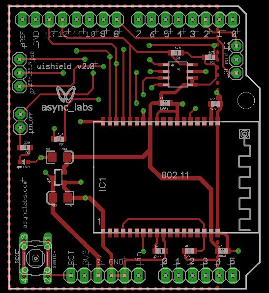
1. WiFi module SPI bus
- Slave Select (SS) : Arduino pin 10 (port B, pin 2)
- Clock (SCK) : Arduino pin 13 (port B, pin 5)
- Master In, Slave Out (MISO) : Arduino pin 12 (port B, pin 4)
- Master Out, Slave In (MOSI) : Arduino pin 11 (port B, pin 3)
2. Interrupt (Uses only one of the following, depending on jumper setting)
- INT0 : Arduino pin 2 (port D, pin 2)
- DIG8 : Arduino pin 8 (port B, pin 0)
3. Interrupt selection jumper
- Allows switching the WiFi interrupt line between INT0 or DIG8
4. WiFi connection status LED: Arduino pin 9 (port B, pin 1)
- Once WiShield is connected to AP or another WiFi device over AdHoc network, LED turns on.
5. LED jumper
- To regain use of digital pin 9, remove the LED jumper cap
6. DataFlash SPI bus
- Slave Select (SS) : Arduino pin 7 (port D, pin 7)
- Clock (SCK) : Arduino pin 13 (port B, pin 5)
- Master In, Slave Out (MISO) : Arduino pin 12 (port B, pin 4)
- Master Out, Slave In (MOSI) : Arduino pin 11 (port B, pin 3)
7. Reset button
- The same as the one on the Arduino board. It resets BOTH the WiShield and Arduino.
Schematic
The schematic can be found here.
If you need software to view the schematic, you can download the Eagle software for free from CadSoft.
Gerber File
The board gerber file can be found here.
Datasheets
The datasheet for the 16Mbit Atmel DataFlash on the WiShield 2.0 is available here.
